(Hong Kong)

Product Summary
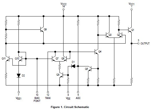
The MC1648P requires an external parallel tank circuit consisting of the inductor (L) and capacitor (C). For Maximum Performance QL≥100 at Frequency of Operation. A varactor diode may be incorporated into the tank circuit to provide a voltage variable input for the oscillator (VCO). The MC1648P was designed for use in the Motorola Phase–Locked Loop shown in Figure 9. This device may also be used in many other applications requiring a fixed or variable frequency clock source of high spectral purity. The MC1648 may be operated from a +5.0Vdc supply or a –5.2Vdc supply, depending upon system requirements.
Parametrics
MC1648P absolute maximum ratings:(1)Power Supply Drain Current, IE: the max value is 41mAdc at the condition of 25℃; (2)Logic “1” Output Voltage, VOH: 4.04 to 4.25Vdc at the condition of 25℃; (3)Logic “0” Output Voltage, VOL: 3.2 to 3.43Vdc at the condition of 25℃; (4)Bias Voltage, VBIAS: 1.45 to 1.75Vdc at the condition of 25℃; (5)Peak–to–Peak Tank Voltage, VP–P: the typ is 400mV at the condition of 25℃; (6)Output Duty Cycle, Vdc: the typ is 50% at the condition of 25℃; (7)Oscillation Frequency, fmax: from 200 to 225MHz at the condition of 25℃.
Features
MC1648P features:(1)Input Capacitance = 6.0pF (TYP); (2)Maximum Series Resistance for L (External Inductance) = 50W (TYP); (3)Power Dissipation = 150mW (TYP)/Pkg (+5.0Vdc Supply); (4)Maximum Output Frequency = 225MHz (TYP).
Diagrams
 |
 MC1648 |
Other |
|
Data Sheet |
Negotiable |
|
||||
|
MC1650 |
Other |
|
Data Sheet |
Negotiable |
|
||||
|
MC1651 |
Other |
|
Data Sheet |
Negotiable |
|
||||
|
MC1658 |
Other |
|
Data Sheet |
Negotiable |
|
||||
|
MC1662 |
Other |
|
Data Sheet |
Negotiable |
|
||||
|
MC1670 |
Other |
|
Data Sheet |
Negotiable |
|
||||